Piping Interview Questions And Answers 25+ Related to Welding & Fabrication for Piping Supervisor, Foreman, Engineer and Inspector
Piping PDF
Piping Interview Questions And Answers Introduction: Understanding Welding & Fabrication in Piping – A Guide for Freshers
Welding and fabrication are two of the most essential processes in the piping industry, especially in sectors like oil & gas, refineries, petrochemicals, and power plants. As a fresher engineering graduate preparing for job interviews, having a basic understanding of these concepts is not just helpful—it’s necessary.
Fabrication involves the cutting, bending, and assembling of pipes, fittings, and supports according to engineering drawings like isometrics or GADs. This is where raw materials are transformed into usable piping systems.
Welding is the process of joining metal parts together using heat or pressure. In piping, it ensures strong and leak-proof connections that can handle high pressures and temperatures.
Even if you’re applying for a general piping or mechanical role (not directly in welding), interviewers often ask questions related to:
Basic welding processes (like SMAW, GTAW, etc.)
Welding procedures (WPS, PQR, WPQ)
Common welding defects and how to detect them
Basic fabrication techniques and industry standards (ASME, API, etc.)
👉 In this article, I’m going to share some basic yet important interview questions and answers related to welding and fabrication that every fresher should know. These will help you understand the practical side of piping work and give you an edge in interviews—especially in the oil & gas and construction sectors.
Let’s begin with the fundamentals and build your confidence step by step. 💪
Q1- What are the different weld layers in piping welding?
Answer:
Weld joints in piping are completed in multiple layers to ensure strength, quality, and proper fusion. The main weld layers are:
Root Pass
This is the first weld layer applied to the joint.
It ensures full penetration and fusion at the root of the joint.
Critical for weld strength and leak-proof performance.
Hot Pass
Applied immediately after the root pass.
Removes slag and smoothens the root to avoid defects.
Helps in bonding the root to the upcoming fill passes.
Fill Pass
Multiple passes added to build up the weld joint thickness.
Fills the remaining groove space.
Provides structural strength to the joint.
Cap Pass (Capping)
Final layer that completes the weld.
Provides a neat finish and reinforces the weld.
Must be smooth, uniform, and free of defects like undercut or overlap.
Q2- What is the accepted misalignment in piping weld joints?
Answer:
Misalignment refers to the offset between the internal surfaces of two pipes or fittings being welded together. It should be within acceptable limits to avoid stress concentration, poor weld quality, and flow restriction.
Accepted misalignment limits are:
1.5 mm – As per ASME B31.3 (Process Piping Code)
This is the general tolerance for high-integrity process piping systems.
It ensures proper alignment for safe operation and smooth fluid flow.
1.6 mm – As per ASME Section IX (Welding Qualification Code)
This standard applies to welder qualification and welding procedure qualification.
Slightly more lenient, as it’s used during test coupons rather than installed piping.
Q3- What is the meaning of ITP (Inspection and Test Plan)?
Answer:
ITP stands for Inspection and Test Plan.
It is a formal document that outlines the step-by-step inspection and testing activities to be carried out on a product, system, or component during manufacturing, fabrication, or installation.
🔍 Key points about ITP:
Describes what will be inspected or tested (e.g., materials, welds, dimensions, pressure tests).
Lists the type of inspection (e.g., visual inspection, dimensional check, NDT, function testing, FAT).
Specifies when and how the inspection will take place during each stage of the project.
Defines the roles and responsibilities of all parties involved (contractor, client, third-party inspector).
Ensures quality control and compliance with applicable codes, standards, and project specifications.
🧾 Typical inspections covered in an ITP:
Raw material inspection
Fit-up and weld visual inspection
Dimensional checks
Non-destructive testing (RT, UT, PT, etc.)
Pressure testing (Hydro/Pneumatic)
Final acceptance inspection or Factory Acceptance Test (FAT)
Q4- What are the four types of inspection stages in quality control? Explain with meaning.
Answer:
In quality control and assurance processes, there are four standard inspection stages that define the level of involvement and responsibility of the QA/QC team during different inspection or testing activities.
These stages are as below:
1. Hold Point (H):
A mandatory inspection stage.
Work must stop until the QA/QC representative is present.
Inspection or testing cannot proceed without approval from QA/QC.
The contractor must notify in advance and wait for QA/QC presence.
Used for critical inspections, such as hydrostatic testing or final visual weld inspection.
✅ Example: Hydrotest should not begin unless the QA/QC inspector is present and gives clearance.
2. Witness Point (W):
QA/QC must be informed in advance about the inspection or test schedule.
However, work can proceed even if the QA/QC representative does not attend.
The activity will still be conducted as scheduled.
QA/QC may choose to attend or skip the inspection.
✅ Example: Fit-up inspection before welding – QA/QC may witness or review later.
3. Surveillance (S):
QA/QC conducts routine or random monitoring of the work in progress.
No prior notice is needed from the construction team.
Ensures continuous quality without disrupting workflow.
Helps identify issues early during fabrication or erection.
✅ Example: QA/QC walks into the fabrication yard and observes welders during their daily work.
4. Review (R):
QA/QC team reviews and approves documents related to quality and inspection.
Includes reviewing WPS, PQR, WPQ, NDT reports, calibration records, and test certificates.
Ensures all documentation is in line with project specifications and codes.
✅ Example: Reviewing NDT reports or welding documentation before final handover.
Inspection Stage
Description
QA/QC Presence Required?
Hold Point
Must stop until QA/QC approves
Yes (mandatory)
Witness Point
QA/QC informed, but not mandatory to attend
Optional
Surveillance
Ongoing monitoring without notice
Not required in advance
Review
Document checking and approval
Yes (off-site or on-site)
Inspection stages in quality control
Q5- What are ‘Specifications’ in piping and construction? Explain.
Answer:
Specifications are detailed written documents that define the technical requirements, construction guidelines, and minimum quality standards for materials, equipment, and workmanship to be followed during a project.
They serve as a reference guide for engineers, contractors, inspectors, and construction teams to ensure that all work meets the design intent, client expectations, and industry codes/standards.
📋 Key Features of Specifications:
Describe materials to be used (type, grade, class, etc.).
Define installation methods and construction procedures.
Specify testing and inspection requirements.
Set acceptance criteria and tolerances.
Mention applicable codes and standards (like ASME, ASTM, API, etc.).
Ensure uniformity and quality assurance across the project.
📌 Purpose of Specifications:
To provide clear guidance to all teams involved in construction or fabrication.
To ensure compliance with safety, reliability, and functional standards.
To serve as a legal and technical document in case of disputes or clarifications.
✅ Example: A piping specification may state that:
All carbon steel pipes must be ASTM A106 Grade B,
Welds must be inspected as per ASME Section V,
and all flange connections must meet ASME B16.5 standards.
Q6- What is P&ID (Piping and Instrumentation Diagram)?
Answer:
P&ID stands for Piping and Instrumentation Diagram. It is a detailed engineering drawing that shows the complete piping layout along with instruments and equipment involved in a specific process system.
It is used in design, construction, commissioning, and maintenance of process plants such as refineries, petrochemicals, oil & gas, and power plants.
📋 What does a P&ID show?
A P&ID includes:
Pipes and Branches
Reducers and Expanders
Valves (Gate, Globe, Ball, Control valves, etc.)
Fittings (Elbows, Tees, etc.)
Process Equipment (Pumps, Vessels, Exchangers, Reactors, etc.)
Instrumentation (Pressure gauges, Temperature indicators, Flow meters, etc.)
Control loops and interlocks
🎯 Purpose of P&ID:
To give a clear representation of the process flow and control.
To help in equipment layout, piping design, and safety reviews (like HAZOP).
To serve as a reference for construction, testing, and maintenance.
To assist operations and troubleshooting of the plant.
✅ Example: A P&ID will show a pump connected to a pipeline, controlled by a pressure control valve, with instruments like pressure transmitter (PT) and temperature indicator (TI) connected to the control system.
Q7- What is WPS (Welding Procedure Specification)?
Answer:
WPS stands for Welding Procedure Specification. It is a formal written document that outlines the detailed welding process and parameters to be followed by the welder to produce quality welds that meet applicable code requirements (like ASME Section IX).
📋 Purpose of WPS:
To provide clear guidance to the welder or welding operator.
To ensure the weld is sound, safe, and meets quality standards.
To maintain consistency and repeatability in welding processes.
To comply with project specifications and relevant codes.
🧾 A WPS typically includes:
Type of welding process (SMAW, GTAW, MIG, etc.)
Base metal and material grade
Filler metal and electrode details
Preheat and post-weld heat treatment (PWHT) requirements
Welding position (1G, 2G, 5G, etc.)
Joint design and thickness range
Welding current, voltage, and travel speed
Shielding gas (if applicable)
✅ Example: A WPS may specify welding a 6mm thick carbon steel pipe using the SMAW process with E6010 electrode for the root pass and E7018 for fill and cap, in the 5G position.
Q8-What is PQR (Procedure Qualification Record)?
Answer:
PQR stands for Procedure Qualification Record. It is a formal record of a test weld that has been performed and tested under controlled conditions to verify that the welding procedure (WPS) will produce a sound and reliable weld that meets code requirements.
A WPS cannot be used in production until it is qualified and supported by a valid PQR.
📋 Purpose of PQR:
To validate that the welding procedure defined in the WPS can produce acceptable welds.
To document the actual welding variables used during the test weld.
To ensure code compliance (e.g., ASME Section IX, AWS D1.1).
🧾 A PQR typically includes:
Details of the test weld (material, thickness, joint type, etc.)
Welding parameters actually used (current, voltage, travel speed)
Type of filler metal and shielding gas
Position and technique used
Test results (e.g., tensile, bend, impact, hardness, macro/micro examination)
Inspector’s certification and approval date
✅ Example: If a company develops a new WPS for welding stainless steel pipes, they must perform a test weld as per the WPS, conduct mechanical testing, and then record the results in the PQR. Only after successful testing can the WPS be used in actual work.
Q9- What is WPQ (Welder Performance Qualification)?
Answer:
WPQ stands for Welder Performance Qualification. It is a certificate or document that proves a welder’s ability to perform a specific welding procedure correctly and in compliance with code requirements, such as ASME Section IX or AWS D1.1.
It confirms that the welder has the skills, knowledge, and hands-on capability to produce sound welds as per the approved Welding Procedure Specification (WPS).
🎯 Purpose of WPQ:
To verify that the welder is qualified to perform welding using a particular process, material, thickness, and position.
To ensure weld quality and safety in production.
To comply with code and project specifications.
🧾 WPQ includes details such as:
Welder’s name and ID number
Welding process (e.g., SMAW, GTAW)
Material type and thickness range
Welding position (1G, 2G, 5G, 6G, etc.)
Type of joint (butt, fillet, groove)
Type of test performed (visual, radiography, bend test, etc.)
Date of qualification and validity period
✅ Example: If a welder successfully performs a 6G pipe welding test using GTAW, and the test passes visual and radiographic inspection, they are issued a WPQ certificate qualifying them for similar welds in production.
Q10- What is the difference between Pipe and Tube?
Answer:
While pipes and tubes may look similar, they are used for different purposes and are measured differently in engineering and fabrication.
📌 Key Differences Between Pipe and Tube:
Feature
Pipe
Tube
Identification
Identified by NB (Nominal Bore)
Identified by OD (Outside Diameter)
Thickness
Measured by Schedule (e.g., SCH 40, SCH 80)
Measured by BWG (Birmingham Wire Gauge) or mm
Purpose
Mainly used for transporting fluids and gases
Used for structural and mechanical applications
Dimensional Tolerance
Less strict tolerance
More precise dimensions and tighter tolerances
Shape
Mostly circular
Can be circular, square, or rectangular
Measurement Example
2” NB Pipe (Nominal size, not actual OD)
50.8 mm Tube (Actual OD)
Difference between pipe and tube
🧾 Explanation:
A pipe is generally used in piping systems to carry liquids or gases and is designed based on pressure and flow rate.
A tube is used in structural applications, instrumentation systems, or heat exchangers, where exact outside diameter and strength are more important.
✅ Example:
A 2-inch pipe has an actual OD of 60.3 mm, and thickness varies based on the schedule.
A 2-inch tube has an OD of exactly 50.8 mm, and the wall thickness is defined in BWG or mm.
Note: tubes are commonly used for heat transfer applications.
✅ Explanation:
In heat exchangers, boilers, condensers, and cooling coils, tubes are preferred over pipes because:
Tubes have precise outer diameter (OD) and uniform wall thickness, which is essential for efficient heat transfer.
They are available in smaller sizes with tighter dimensional tolerances, allowing for compact and optimized designs.
Tubes can be made from high thermal conductivity materials like copper, stainless steel, and brass, which improve heat exchange performance.
🧪 Examples of heat transfer applications using tubes:
Shell and tube heat exchangers – Tubes carry one fluid while the shell carries another, allowing heat exchange across the tube wall.
Boiler water tubes – Carry water or steam for heating.
Condenser tubes – Used in power plants and refrigeration systems.
Finned tubes – Used to increase surface area and enhance heat transfer.
Q11- What are the main duties of a Piping Inspector?
Answer:
A Piping Inspector plays a crucial role in ensuring that all piping activities—such as fabrication, installation, inspection, and testing—are performed according to project specifications, international standards (like ASME B31.3), and approved procedures.
Below are the main duties and responsibilities of a piping inspector:
🔍 1. Material Receiving & Inspection
Verify material grade, size, quantity, and heat numbers.
Ensure materials comply with approved Material Test Certificates (MTCs).
🧊 2. Storage & Preservation
Ensure proper storage to avoid damage or corrosion.
Confirm that caps are placed on pipe ends and materials are stored as per procedure.
✂️ 3. Cutting, Assembly & Fit-Up Inspection
Check marking, cutting methods, and fit-up before welding.
Verify root gaps, edge preparation, and alignment.
🔧 4. Pre-Welding Inspection
Ensure correct WPS, welder qualifications (WPQ), and electrode storage.
Check interpass temperature, cleanliness, and preheat requirements.
👁️ 5. Visual Inspection of Socket & Threaded Joints
Check for proper engagement, thread sealant, and fitment.
💨 6. Pneumatic Test for Reinforcing Pad
Witness leak tests on reinforcement pads (pads around branch connections).
🧼 7. Pickling & Passivation
Inspect chemical cleaning of stainless steel pipes to remove weld burns and contamination.
💻 8. Database Reporting & Documentation
Record inspection results, test reports, and daily progress in the quality database or logbook.
🔍 9. Visual Inspection of Completed Spools
Ensure completed pipe spools meet drawing dimensions and have proper weld quality.
🏗️ 10. Piping Pre-Inspection & Spool Erection
Inspect correct orientation, supports, and spool placement during installation.
🔎 11. Orifice Flange Inspection
Ensure correct installation of orifice plates and pressure taps, with the flow direction clearly marked.
📐 12. Pipe Support Inspection
Verify support type, spacing, clamps, and anchor points as per drawings.
📏 13. Verification of Slope
Check slope in sloped lines (e.g., drain, vent, or process lines) using spirit levels or lasers.
🧽 14. Internal Cleanliness
Confirm pipes are free from dirt, debris, rust, or welding slag before closing or hydrotesting.
🔩 15. Valve Installation
Ensure valves are installed in correct orientation and accessible for operation.
🧯 16. Flange Joint Inspection
Check gasket type, bolt tightening sequence, and surface finish.
📋 17. Pre-Test Punch Listing
Generate punch list of incomplete items before pressure testing.
💧 18. Hydrostatic or Pneumatic Testing
Witness testing as per approved test packs and verify test pressure, hold time, and leak check.
🚀 19. Pre-Commissioning Activities
Ensure systems are cleaned, flushed, and preserved before handing over to operations.
Q12- How many types of gaskets do you know? Explain briefly.
Answer:
Gaskets are sealing materials or elements placed between two flange faces to prevent leakage of fluids or gases under pressure. They are selected based on pressure, temperature, fluid type, and flange design.
Here are the commonly used types of gaskets in piping systems:
🔹 1. Full Face Gasket (Asbestos / Non-Asbestos)
Covers the entire flange face, including the bolt holes.
Typically used in low-pressure systems and flat face flanges.
Asbestos gaskets are now mostly replaced by non-asbestos alternatives due to health concerns.
🔹 2. Spiral Wound Gasket (Metallic)
Made of alternating layers of metal windings and soft filler material (like graphite or PTFE).
Used in high-pressure and high-temperature applications.
Provides excellent sealing and recovery properties.
Commonly used with raised face flanges.
🔹 3. Ring Type Gasket (RTJ – Ring Type Joint)
Solid metal ring used in Ring Type Joint flanges (RTJ flanges).
Suitable for very high-pressure and high-temperature environments.
Commonly used in oil & gas, refinery, and offshore industries.
🔹 4. Metal Jacketed Gasket
Consists of a soft filler (like graphite) enclosed in a metal jacket.
Offers the benefits of both metal and soft gaskets.
Used in heat exchangers, high-temp piping, and special applications.
🔹 5. Inside Bolt Circle (IBC) Gasket / Raised Face Gasket
Covers only the sealing surface inside the bolt holes (inside bolt circle).
Commonly used with raised face flanges.
Requires proper alignment to avoid leakage.
🔍 In simple words: Gaskets come in different types to match the flange type, pressure, and temperature of the system. Choosing the right gasket is critical for leak-proof and safe operations.
Q13- How are gaskets classified based on materials? Explain with examples.
Answer:
Gaskets are also classified based on the material they are made from, which determines their chemical resistance, temperature limit, pressure handling, and application suitability.
Below are the main categories of gaskets based on materials:
🔹 1. Non-Metallic Gaskets (Soft Gaskets)
Made from compressible materials like rubber, graphite, PTFE, CNAF (Compressed Non-Asbestos Fiber), etc.
Used for low to medium pressure and temperature applications.
Provide excellent sealing where flanges are not perfectly smooth.
Examples:
Asbestos (now mostly replaced due to health risks)
Non-asbestos fiber gaskets (CNAF)
Rubber gaskets (Neoprene, EPDM)
PTFE (Teflon) – for chemical resistance
Graphite – suitable for high temperature up to 500°C
✅ Common Use: Water, air, oil, chemicals in low-pressure pipelines
🔹 2. Semi-Metallic Gaskets
A combination of metal and soft sealing materials.
Provide a balance of strength and flexibility.
Suitable for medium to high pressure and temperature.
Examples:
Spiral wound gaskets – made with stainless steel and graphite/PTFE filler
Metal jacketed gaskets – soft filler inside a metallic cover
✅ Common Use: Heat exchangers, pressure vessels, high-temp piping
🔹 3. Metallic Gaskets (Hard Gaskets)
Made entirely from metal such as stainless steel, Inconel, Monel, or soft iron.
Used in high-pressure, high-temperature, and critical services.
Require RTJ (Ring Type Joint) flanges with precise surface finish.
Examples:
RTJ (Ring Type Joint) gaskets – R-type, RX, and BX designs
Solid metal gaskets for specialized sealing
✅ Common Use: Refineries, offshore platforms, petrochemical plants
📌 Gasket Material Selection Depends On:
Operating pressure and temperature
Type of fluid/gas (corrosive, flammable, toxic)
Flange face type (RF, FF, RTJ)
Required sealing performance and durability
🔍 In simple words: Gasket materials range from soft non-metallics (like rubber or graphite) to strong metallic types. The right material ensures leak-proof joints in various pressure, temperature, and chemical environments.
Q14- What are the different types of mating flanges? Name and explain the 4 most common types.
Answer:
Mating flanges refer to the two flange faces that come into contact and are bolted together with a gasket in between to form a leak-tight joint.
The type of flange face determines the gasket type, sealing surface, and pressure class compatibility.
Here are the 4 most common flange face types used in piping systems:
🔹 1. Flat Face (FF) Flange
The entire face of the flange is flat.
Requires a full-face gasket.
Commonly used in low-pressure systems and where the mating flange is made of cast iron or plastic.
✅ Used in: Water lines, firefighting systems, and utility services.
🔹 2. Raised Face (RF) Flange
The sealing area is raised slightly (1.6 mm or 6.4 mm) above the bolt circle face.
A gasket is placed only on the raised face area, reducing gasket contact area and improving sealing under pressure.
Most common flange type in process and industrial piping.
✅ Used in: Oil & gas, petrochemicals, power plants.
🔹 3. Ring Type Joint (RTJ) Flange
Has a machined groove on the flange face for a metallic ring gasket.
Provides a metal-to-metal seal for very high-pressure and high-temperature services.
Requires precise installation and special RTJ gaskets.
✅ Used in: Offshore, refineries, high-pressure lines.
🔹 4. Tongue & Groove (T&G) Flange
One flange has a raised ring (tongue), the other has a matching depression (groove).
The gasket is seated inside the groove, providing self-alignment and better gasket retention.
Helps avoid gasket blow-out in moderate to high-pressure systems.
✅ Used in: Heat exchangers, high-integrity joints, critical fluid lines.
🔹 Other Mating Flange Face Types (Less Common):
🔸 Male & Female (M&F) Flange
Similar to T&G, but the male face is flat and protrudes, and the female face has a recess.
Gasket sits in the female part for accurate alignment and sealing.
Used in systems where repeated disassembly is not common.
📌 Comparison Table:
Flange Face Type
Gasket Type Used
Pressure Rating
Key Feature
Flat Face (FF)
Full Face Gasket
Low
Simple, flat contact
Raised Face (RF)
Ring Gasket
Low to High
Most common, good seal efficiency
RTJ
Metallic Ring Gasket
Very High
Metal-to-metal seal
Tongue & Groove
Special T&G Gasket
Medium to High
Prevents gasket blowout
Male & Female
Confined Gasket
Medium
Self-aligning faces
🔍 In simple terms: The type of flange face determines how the gasket seals and how strong and leak-proof the connection is under different pressure and temperature conditions.
Q15- What are the different types of flanges based on construction?
Answer:
Flanges are also classified based on how they are constructed or connected to the piping system. Each type of flange is selected based on pressure, temperature, pipe material, and service conditions.
Here are the most commonly used flange types based on construction:
🔹 1. Weld Neck Flange (WNF)
Has a long tapered neck that is butt-welded to the pipe.
Provides excellent strength, stress distribution, and is suitable for high-pressure, high-temperature applications.
Commonly used in critical process piping.
✅ Used in: Refineries, chemical plants, high-temperature lines.
🔹 2. Slip-On Flange (SOF)
The pipe is inserted into the flange and fillet-welded on both the inside and outside.
Easier to align but less strong than weld neck flanges.
Suitable for low to medium pressure applications.
✅ Used in: Water lines, cooling systems, fire-fighting systems.
🔹 3. Socket Weld Flange (SWF)
Has a recessed socket where the pipe is inserted and then fillet welded.
Commonly used for small diameter, high-pressure piping.
Provides good strength but not as strong as weld neck flanges.
✅ Used in: Hydraulic systems, steam lines, chemical processing.
🔹 4. Threaded Flange (Screwed Flange)
Has internal threads and is screwed onto the pipe without welding.
Suitable for low-pressure, non-critical services where welding is not possible.
Not recommended for high temperature or vibration-prone lines.
✅ Used in: Utility lines, water supply, compressed air systems.
🔹 5. Lap Joint Flange (LJF)
Used with a stub end; the flange itself is not welded to the pipe.
Allows rotation for easy alignment of bolt holes.
Suitable for systems where frequent disassembly is required.
Low-pressure use only.
✅ Used in: Food processing, pharmaceutical, and systems with exotic materials.
🔹 6. Blind Flange (BLF)
A solid disk with bolt holes, used to close the end of a pipe, valve, or equipment.
Can be easily removed for inspection or future expansion.
Can handle high-pressure due to solid construction.
✅ Used in: Line terminations, testing, future expansions.
🔹 7. Orifice Flange
Special flange pair with tap holes for installing an orifice plate and measuring flow.
Comes with pressure tap ports for pressure drop monitoring.
✅ Used in: Flow measurement systems in process industries.
📌 Summary Table:
Flange Type
Welding Method / Connection
Pressure Rating
Common Use
Weld Neck
Butt weld
High
Critical process piping
Slip-On
Fillet weld (inside & outside)
Medium
Water lines, utility systems
Socket Weld
Fillet weld (only outside)
High (small bore)
Small-diameter high-pressure
Threaded
Screwed (no welding)
Low
Non-critical low-temp systems
Lap Joint
Used with stub end
Low
Easy disassembly
Blind
No pipe (end closure)
High
Line isolation
Orifice
With orifice plate & taps
Medium–High
Flow measurement
🔍 In simple words: Flanges are chosen based on how they connect to the pipe (welding, threading, or bolting) and what pressure or service condition they must handle.
Q16- What type of information do you get from Isometric Drawings?
Answer:
An Isometric Drawing is a piping fabrication and installation drawing that represents a 3D view on a 2D paper, showing all necessary details of a pipeline section.
It is widely used in construction, inspection, and fabrication because it provides complete technical information about the piping line in a simplified format.
📋 Key Information Provided by an Isometric Drawing:
🔹 1. Line Routing and Orientation
Shows the exact path the pipe takes in three dimensions (horizontal, vertical, inclined).
🔹 2. Northing, Easting & Elevation
Indicates the coordinates and pipe elevation levels to match the actual site layout.
🔹 3. Bill of Materials (BOM)
Lists all components like pipes, elbows, tees, reducers, valves, gaskets, flanges, etc., required for that isometric.
🔹 4. Insulation Type
Specifies whether the line requires thermal insulation, acoustic insulation, or painting, and the type/material.
🔹 5. NDT (Non-Destructive Testing) Requirements
Mentions the type and extent of NDT (e.g., 100% Radiography, PT, UT) for weld joints.
🔹 6. Revision Status
Tracks drawing revisions with version numbers, dates, and changes made.
🔹 7. Material Classification
Identifies the material class (e.g., CS, SS, Alloy) as per project specification.
🔹 8. Design, Operating & Test Pressure/Temperature
Specifies the design conditions to select suitable pipe materials and test limits.
🔹 9. Paint or Coating System
Provides paint specification or coating system (e.g., epoxy, galvanized) for corrosion protection.
🔹 10. P&ID Reference
Links the isometric drawing to the parent P&ID (Piping & Instrumentation Diagram).
🔹 11. Slope / Drain Details
Indicates required slope direction and gradient for lines like drains, vents, and sloped pipelines.
🔹 12. Service Details
Tells what fluid or gas the line carries (e.g., steam, water, oil, nitrogen).
🔹 13. Flow Direction
Shows arrow marks to indicate the direction of fluid flow in the line.
🔹 14. Pipe Support Details
Highlights locations and types of supports, such as hangers, guides, or shoes.
🔹 15. General Notes / Special Instructions
Additional instructions like welding sequence, spool splitting, or vendor notes.
🔍 In simple words: An isometric drawing is the blueprint that tells you what to build, how to build, and with what materials—making it essential for fabricators, inspectors, and engineers on site.
Q17- What types of codes and standards do you use as a Piping Inspector?
Answer:
As a Piping Inspector, your work must comply with recognized international codes and standards to ensure safety, quality, and technical correctness in piping design, fabrication, installation, testing, and inspection.
Below are the main international codes and standards commonly used in the piping industry:
📘 ASME Codes (American Society of Mechanical Engineers):
🔹 ASME B31.3 – Process Piping
The most widely used code in refineries, chemical, petrochemical, and gas processing plants.
Covers design, materials, fabrication, inspection, testing, and safety of process piping systems.
🔹 ASME B31.1 – Power Piping
Used in power plants and boiler systems, handling high-pressure steam and water.
🔹 ASME B31.5 – Refrigeration Piping and Heat Transfer Components
Applies to industrial and commercial refrigeration systems including piping, components, and safety requirements.
🔹 ASME B31.9 – Building Services Piping
Covers low-pressure piping systems for heating, air conditioning, plumbing, and ventilation inside buildings.
🔹 ASME Section IX – Welding Qualification
Governs the qualification of welding procedures (WPS, PQR) and welder performance (WPQ).
Essential for ensuring weld quality and compliance with construction codes.
🔹 ASME Section V – Nondestructive Examination (NDE)
Provides requirements and guidelines for NDT methods like Radiographic Testing (RT), Ultrasonic Testing (UT), Magnetic Particle Testing (MT), and Dye Penetrant Testing (PT).
🔹 ASME Section II – Materials
Covers specifications for materials including mechanical properties, chemical composition, and testing standards.
🌍 Other International Standards and Guidelines:
🔹 API (American Petroleum Institute)
API 570 – Piping Inspection Code (used for in-service inspection)
API 574 – Inspection Practices for Piping System Components
API 5L – Specification for Line Pipe
API 6D – Specification for Valves
🔹 ASTM (American Society for Testing and Materials)
Provides standards for materials, testing, and mechanical properties (e.g., ASTM A106, ASTM A105, ASTM A312)
🔹 ISO Standards (International Organization for Standardization)
ISO 9001 – Quality Management Systems
ISO 14692 – For GRP piping systems
🔹 AWS (American Welding Society)
AWS D1.1 – Structural Welding Code for Steel
Commonly referred to for welding practices and symbols
🛠️ Why These Codes Matter for a Piping Inspector:
Ensure compliance with international safety and quality standards
Enable proper inspection, testing, and documentation
Maintain uniformity across global projects
Prevent failures by adhering to recognized engineering practices
🔍 In simple words: A piping inspector must follow globally recognized codes like ASME, API, ASTM, AWS, and ISO to ensure that all piping work is technically correct, safe, and of high quality.
Q18- What are the types of valves used in piping systems?
Answer:
Valves are essential components in a piping system. They are used to start, stop, control, or regulate the flow of fluids (liquids or gases). Valves are classified based on their design, function, and application.
🔹 Common Types of Valves (Based on Design):
1. Gate Valve
Used for on/off service (full open or full close).
Not suitable for throttling.
Operates by lifting a gate out of the fluid path.
Provides minimal pressure drop when fully open.
✅ Use: Isolation of fluid in pipelines.
2. Globe Valve
Designed for flow regulation.
Offers better control than gate valves.
Has higher pressure drop due to flow direction change.
✅ Use: Throttling and flow control applications.
3. Butterfly Valve
Rotating disc controls the flow.
Compact, lightweight, and suitable for large pipes.
Quick to open/close.
✅ Use: Low-pressure applications, water lines, ventilation.
4. Check Valve (Non-return Valve)
Allows flow in one direction only.
Prevents backflow in the system.
No external control needed.
✅ Use: Pump discharge, compressor lines.
5. Needle Valve
Precise control of flow using a slender, needle-like plunger.
Best for fine regulation of flow in small pipelines.
✅ Use: Instrumentation and lab systems.
6. Control Valve
Operated automatically to regulate pressure, temperature, or flow.
Often integrated with actuators and sensors.
✅ Use: Process control systems in industries.
7. Knife Gate Valve
Has a sharp-edged blade to cut through thick or viscous fluids.
Good for slurry, wastewater, or pulp applications.
✅ Use: Mining, chemical, and waste treatment plants.
🔸 Classification Based on Function:
Function Type
Explanation
Examples
Isolation Valve
Used to completely stop the flow when required
Gate, Ball, Butterfly
Regulation Valve
Used to control or throttle the flow rate
Globe, Needle, Control
Non-Return Valve
Prevents backflow in a pipeline
Check Valve
Special Purpose Valve
Designed for specific fluids or conditions
Knife Gate, Pressure Relief
📌 Quick Summary Table:
Valve Type
Main Purpose
Manual / Automatic
Used For
Gate Valve
Isolation (On/Off)
Manual
Oil, gas, water, steam lines
Globe Valve
Flow regulation
Manual
Fuel, water, chemical processes
Butterfly Valve
Quick isolation
Manual / Auto
HVAC, water treatment, large pipelines
Check Valve
Backflow prevention
Automatic
Pumps, compressors
Needle Valve
Precise flow control
Manual
Instrumentation systems
Control Valve
Automated regulation
Automatic
Process control loops
Knife Gate Valve
Handling slurries
Manual / Pneumatic
Pulp, mining, wastewater
🔍 In simple words: Valves are chosen based on what they need to do — stop flow, control flow, or prevent reverse flow — and each valve has its own design suited to specific conditions.
Q19- What are the main things you will check before bolt torqueing?
Answer:
Before performing bolt torquing on a flange joint or any mechanical connection, a piping inspector or technician must ensure certain parameters are checked and verified to achieve the desired tightness, leak-free sealing, and safety compliance.
Here are the main things to check before bolt torquing:
🔹 1. Correct Bolt Size and Material
Verify the bolt size, length, diameter, and grade as per the flange specification.
Ensure compatibility with flange pressure rating and design standard (e.g., ASME B16.5).
🔹 2. Calibration Status of Torque Wrench
Ensure the torque wrench (manual or hydraulic) is calibrated and within valid certification date.
Calibration certificates must be available and traceable.
🔹 3. Torque Tool Type – Manual or Hydraulic
Choose the appropriate tool based on bolt size and torque requirement:
Manual torque wrench for small to medium bolts.
Hydraulic torque tools for large-diameter, high-torque flanges.
🔹 4. Lubricant Application
Verify that approved thread lubricant (anti-seize compound) is applied on bolt threads and under the nut face.
This reduces friction and ensures accurate torque transfer.
🔹 5. Friction Factor Consideration
Consider the friction factor of the lubricant when calculating torque.
Friction affects the actual preload applied to the bolts, which influences gasket sealing.
🔹 6. Torque Value Confirmation
Confirm the torque value as per flange standard or engineering instruction (e.g., ASME PCC-1 guidelines).
Follow the torque-tightening sequence (typically a star pattern) and staging method (in multiple passes).
🔹 7. Cleanliness of Flange Faces and Bolts
Ensure that flange surfaces, threads, and gasket seating areas are clean and free from dirt, rust, or debris.
Contamination can affect sealing and bolt load accuracy.
🔹 8. Gasket Type and Position
Confirm the correct gasket is installed and properly centered between the flange faces.
Also refer to standards like ASME B16.5, ASME B16.47, and company-specific procedures if required.
🔍 In simple words: Before torqueing, check the tools, bolts, lubricant, gasket, torque values, and cleanliness to ensure a leak-proof and safe flange joint.
Q20- Hydrostatic Test Punch List Items Prior to Commencing Hydrotest at Site.
Before conducting a hydrostatic pressure test on any piping system, it is critical to ensure that all preparatory and safety conditions are fully met. Below is a comprehensive checklist of items that must be verified and completed before starting the test:
🔧 Pre-Hydrotest Punch List Items
All hot work shall be completed ➤ All welding, cutting, or grinding must be fully finished before testing to ensure no structural changes during or after testing.
Strainers shall be removed ➤ Temporary strainers, filters, and internal components susceptible to damage must be removed prior to hydrotest.
All NDT (Non-Destructive Testing) & DT (Destructive Testing) shall be completed ➤ All welds must be inspected and accepted as per project specifications and applicable codes (e.g., ASME B31.3).
PWHT (Post Weld Heat Treatment) shall be completed ➤ All joints requiring heat treatment must have it completed and documented before pressure testing.
Adequate pipe supports and attachments shall be installed ➤ Both permanent and temporary supports must be in place to maintain pipe alignment and prevent sagging or stress.
Coating on weld joints shall be removed ➤ All painted or coated areas covering the welds must be cleaned to allow visual leak detection during the test.
Calibration of all testing equipment shall be verified ➤ Pressure gauges, torque wrenches, and other tools must be calibrated and have valid certification. ➤ Test blind flanges must have material test certificates (MTCs).
Test fluid certificates shall be reviewed and accepted ➤ The hydrotest medium (typically clean water) should be non-corrosive and free from contaminants, especially for stainless steel systems.
Sensitive internal components shall not be installed ➤ Devices such as orifice plates, flow nozzles, sight glasses, and similar instruments that could interfere with filling, venting, or draining must be removed or not yet installed.
All flange, threaded, and welded joints shall be left exposed ➤ No insulation, wrapping, or obstruction is allowed. Visual inspection of all joints for leaks is mandatory during the strength test.
Flange joints must be inspected, and gasket material verified and properly torqued ➤ Ensure correct gasket installation and torque values are applied in accordance with torque charts or specifications.
Drains shall be provided at all low points of the piping system ➤ Proper drainage points ensure complete removal of water after the test.
Vents and drain valves (temporary or permanent) must conform to the piping class/rating ➤ Ensures compatibility and safety during pressurization and depressurization.
Pipe supports are installed as per design ➤ Temporary supports may be added if needed to prevent pipe displacement during testing.
Expansion joints, spring hangers, and supports must be temporarily restrained ➤ Prevents movement or damage during test pressure application.
Arc strikes, gouges, or other poor workmanship signs must be removed and inspected ➤ Surface defects must be ground smooth and re-inspected using MT (Magnetic Particle Testing) or PT (Penetrant Testing).
Drains provided immediately above vertical check valves ➤ Prevents trapped air or fluid that could affect test accuracy or valve performance.
All threaded joints up to the first block valve in hydrocarbon systems are seal welded ➤ Ensures no leakage from threaded connections. Thread engagement must also be verified.
Pressure testing manifold is pre-tested ➤ The manifold should be pressure tested separately to at least 1.2 times the intended test pressure, or not less than the discharge pressure of the test pump.
Line compliance with isometric drawings is confirmed: i. Material grade/schedule matches Bill of Materials ii. Flange and fittings ratings are correct iii. Construction tolerances are met as per project standard
📌 Conclusion:
Performing the above checks ensures:
Test safety
Leak-free performance
Code and project compliance
Long-term piping reliability
Bonus Items (Recommended to check):
✅ All gaskets and torques verified and flange joints properly aligned.
✅ Drains at low points and vents at high points are installed and accessible.
✅ Temporary supports or restraints installed on expansion joints or spring supports.
✅ Arc strikes and weld defects are ground and inspected (MT/PT).
✅ Ensure line complies with Isometric drawing, material class, and construction tolerances.
Q21- Which type of documents/reports are attached in a hydrostatic testpackage?
Answer:
A Hydrostatic Test Package (HTP) is a collection of documents that verifies a piping system has been tested according to project specifications, international codes (e.g., ASME B31.3), and client requirements. These documents serve as official records and ensure compliance, traceability, and quality assurance.
📁 Documents/Reports Included in a Hydrostatic Test Package:
Hydrotest Procedure ➤ Approved method statement or procedure describing how the test is conducted.
Hydrotest Clearance/Permit ➤ Approved permit from QA/QC, operations, or safety department authorizing the test.
Approved P&ID and Isometric Drawings ➤ Marked-up or test-approved drawings showing line identification, test boundaries, and any modifications.
Line Check Reports / Punch List Clearance ➤ Verified documentation showing that the line has been physically inspected and all punch items are cleared.
Test Pressure Calculation Sheet ➤ Document showing the design pressure, test pressure, test duration, and applicable code reference (e.g., ASME B31.3 formula).
Calibration Certificates of Pressure Gauges and Recorders ➤ Valid certificates for all measuring instruments used in the test.
Flange Management Checklist / Bolt Torque Records ➤ Records showing all flanged connections were assembled, torqued, and inspected properly.
Material Test Certificates (MTCs) for Test Blinds and Components ➤ Certification for test blinds, temporary fittings, or materials used during testing.
Test Fluid Certificate (Water Quality Report) ➤ Report verifying that the test fluid used (e.g., water) is clean and suitable for the tested material (non-corrosive).
Test Manifold Pressure Test Report ➤ Documentation confirming that the test manifold was pre-tested to required pressure.
Pressure Test Log Sheet / Chart Recorder Graph (if used) ➤ Actual test data showing:
Start and end time
Test pressure
Ambient temperature
Any drop in pressure
Signature of inspectors and witnessing authorities
Visual Inspection Report Post-Hydrotest ➤ Confirmation that all joints were visually inspected for leaks and condition after testing.
Photographic Evidence (if applicable) ➤ Photos of gauge readings, joint conditions, or any special test setups.
Witness / Approval Signatures ➤ Sign-off by contractor, client, QA/QC, and third-party (if required) confirming successful test.
Test Acceptance Certificate ➤ Final document confirming that the system passed the hydrostatic test and is accepted for further process (e.g., insulation or commissioning).
📌 Note:
All documents must be properly numbered, signed, dated, and stamped as per the project’s document control system.
The Hydro Test Package becomes part of the Mechanical Completion Dossier or Turnover Package to the client.
Q22- What is the size and location of weep holes in dummy pipe supports?
Answer:
Weep hole size shall be drilled to 6 mm diameter.
For vertical dummy supports: The weep hole shall be located near the base plate.
For horizontal dummy supports: The weep hole shall be located at the 6 o’clock position (bottom) near the run pipe.
📌 Purpose of Weep Hole:
Weep holes are provided to:
Drain moisture or water trapped inside the dummy leg or pipe support.
Prevent corrosion and rust buildup inside the closed section of support.
Maintain structural integrity and prolong the support’s life.
Q23- What is a Dead Leg in Piping? Explain with Definition and Criteria.
Answer:
A Dead Leg in piping refers to a section of pipe or branch where fluid flow is stagnant or very minimal, which can lead to internal corrosion, bacterial growth, or solid deposition over time.
📌 Key Points:
Dead legs are areas in a piping system where no regular flow occurs.
Common in unused branches, blind ends, or instrument tappings.
They pose a risk of corrosion due to trapped moisture, settled solids, or lack of flushing.
Regular monitoring and inspection are necessary to prevent failure.
📏 Dead Leg Criteria (General Guidelines):
For pipes ≥ 2 inches (NPS):
A section is considered a dead leg if its length is greater than 3 times its diameter, or longer than 1.22 meters (4 feet).
Length is measured from the outer diameter of the main (header) pipe to the near end of the branch valve.
For branch connections ≤ 1½ inches (NPS):
The dead leg length is measured from the end of the boss (stub-in) to the near end of the valve.
🔧 Common Causes of Dead Legs:
Unused nozzles or valves left closed
Instrument tappings not in continuous use
Sampling lines with infrequent draw
Incorrect design with long stub pipes or capped tees
⚠️ Why Dead Legs Are a Concern:
Corrosion Risk: Trapped water can corrode carbon steel internally.
Microbial Growth: Especially in water lines (MIC – Microbiologically Influenced Corrosion).
Process Contamination: If reintroduced into the main line, it may carry rust, debris, or contaminants.
🛡️ Prevention and Management:
Minimize or eliminate dead legs in design.
Ensure regular flushing or cleaning during operation.
Use corrosion-resistant materials for unavoidable dead legs.
Include dead legs in inspection and corrosion monitoring programs.
Q24- What are the Types of Piping Supports?
Answer:
Piping supports are essential components used to carry the weight of the pipe, maintain alignment, absorb thermal expansion, and reduce vibration or movement due to internal pressure, wind, or seismic activity.
Here are the common types of piping supports used in industries:
🔧 1. Pipe Shoe
A pipe shoe is a rigid support that lifts the pipe above the supporting structure.
It allows for thermal movement, avoids direct metal-to-metal contact, and helps in load distribution.
Commonly used for insulated or hot piping.
🔧 2. Resting Support (Saddle or Base Support)
A simple support where the pipe rests on a beam, rack, or steel base.
Allows for vertical load-bearing only.
Used for horizontal lines where no axial movement restriction is needed.
🔧 3. Spring Support (Variable or Constant Load)
Used where pipe expands/contracts vertically due to thermal movement.
Maintains a constant or variable load while allowing vertical movement.
Variable Spring Hanger: Load changes with movement.
Constant Spring Hanger: Load remains the same throughout movement.
🔧 4. Wear Pad (or Cladding Pad)
A reinforcement plate welded to the pipe’s outer surface.
Prevents abrasion or wear between the pipe and support.
Used in areas of frequent vibration or sliding contact.
🔧 5. Hanger Support
Suspends the pipe from the structure above using rods or clamps.
Used in overhead piping layouts.
Allows free movement and absorbs expansion/contraction.
🔧 6. Guide Support
Allows axial movement but restricts lateral movement.
Maintains pipe alignment during expansion or vibration.
Often used in long straight pipe runs.
🔧 7. Anchor Support
Fixes the pipe in all directions — restricts both movement and rotation.
Used at key points to control expansion forces.
Typically installed near pumps, tanks, or equipment nozzles.
🔧 8. Clamp Support (Rigid Clamp or Sliding Clamp)
Clamps the pipe without allowing movement (rigid) or permits sliding with low friction (sliding).
Prevents vibration or movement.
🔧 9. Trunnion Support
A short vertical pipe welded to the main pipe.
Transfers loads to a base or structure.
Common in high-temperature piping systems.
🔧 10. Dummy Leg (or Stub Support)
A short piece of pipe attached at an elbow or branch, resting on the structure.
Helps in supporting change in direction in horizontal lines.
📌 Conclusion:
The choice of piping support depends on:
Pipe size, temperature, and material
Required movement allowance
Structural layout and load conditions
Q25- What type of connection is acceptable for a 24” header and a 12”branch?
Answer:
For a 24-inch header with a 12-inch branch, the acceptable types of connections are:
Weldolet
A branch connection fitting that provides a smooth transition from header to branch.
Commonly used for large-size-on-size or reducing branches.
Designed to handle high pressure and temperature, with good reinforcement.
Welded Branch with Reinforcement Pad (Re-pad)
A direct welded branch connection (e.g., tee or stub-in) with a reinforcement pad welded around the branch area.
Required when the branch size is 50% or more of the header size, as per ASME B31.3.
The re-pad provides structural strength to compensate for the metal removed during cutting.
📏 Why Reinforcement is Important:
A 12” branch on a 24” header is a 50% branch, which is considered large, and may weaken the header if not reinforced.
Therefore, either a Weldolet (which is self-reinforcing) or a welded branch with an added reinforcement pad is needed to:
Maintain pressure integrity
Comply with piping code requirements
Ensure safe operation
📌 Conclusion:
✅ Acceptable connection types for 24″ header × 12″ branch:
Weldolet
Welded branch with reinforcement pad (stub-in with re-pad)
Both options are valid and selection depends on design code, stress analysis, material availability, and client specifications.
Q26- How many minimum pressure gauges are required to be installedduring a hydrostatic test?
Answer: Two pressure gauges must be installed as a minimum.
📌 Explanation:
According to standard practice and most project specifications (including ASME and API guidelines):
At least two calibrated pressure gauges should be installed during a hydrostatic test.
This ensures accurate and reliable pressure monitoring throughout the test.
✅ Typical Installation Locations:
At the highest point of the test section ➤ Helps detect any trapped air and gives a clear pressure reading at the top of the line.
Near the pump or test manifold (lowest point) ➤ Ensures pressure at the source is monitored and helps detect any pressure drop or fluctuation.
🛠️ Important Notes:
Both gauges must have valid calibration certificates.
The gauges should have a range of 1.5 to 2 times the test pressure for accuracy.
Some specs may require more than two gauges based on the length, complexity, or diameter of the piping system.
Q27- Write Hydrostatic Test Procedure for Piping Systems
📌 1. Objective:
To verify the integrity and strength of the piping system by applying pressurized fluid (usually water) and ensuring there are no leaks or pressure drops.
📌 2. References:
ASME B31.3 (for Process Piping)
Project Specifications
Approved Isometric Drawings & P&IDs
ITP (Inspection & Test Plan)
📌 3. Equipment and Materials Required:
Calibrated pressure gauges (minimum two)
Hydrotest pump (manual or motorized)
Temporary test blinds, gaskets, and bolts
Test fluid (usually clean water)
Vent and drain valves
Hoses and manifolds
Safety PPE (goggles, gloves, barriers)
📌 4. Pre-Test Checklist:
✔️
Item
✅
All welding, NDT, and PWHT completed
✅
Flange bolts torqued, gaskets installed correctly
✅
Test blinds and temporary vents/drains installed
✅
Air removed using vents
✅
Expansion joints isolated or restrained
✅
Pressure gauges calibrated (range: 1.5 to 2x test pressure)
✅
Test water is clean and approved
✅
Piping system cleaned and flushed
✅
Adequate pipe supports installed
✅
Line inspected against approved isometric drawings
📌 5. Test Procedure:
Fill the system slowly with water through a low point drain or filling valve. ➤ Ensure air is completely vented from high points.
Apply test pressure using the hydrotest pump. ➤ Bring pressure gradually to the required test pressure (usually 1.5 times design pressure as per ASME B31.3).
Stabilize the pressure ➤ Hold the pressure for a minimum of 10 minutes or as per client/project specs.
Inspect the system visually ➤ Check for leaks, flange seepage, weld sweating, or gauge drops.
Record readings ➤ Note start/end time, ambient temperature, pressure reading, and inspector’s observations.
📌 6. Acceptance Criteria:
No pressure drop (within acceptable limit).
No leakage observed at welds, flanges, or fittings.
Gauges show stable pressure throughout the test duration.
📌 7. Post-Test Activities:
✔️
Task
✅
Release pressure slowly and safely
✅
Drain the test fluid completely
✅
Remove test blinds, reinstall normal gaskets
✅
Reinstall any removed strainers or instruments
✅
Re-dry the lines (especially for stainless steel)
✅
Restore pipe supports and insulation (if removed)
✅
Complete documentation and sign-off
📌 8. Documentation in Test Package:
Hydrotest Procedure
Hydrotest Clearance & Permit
Isometric Drawing (marked for test limit)
Pre-test Punch List Clearance
Pressure Gauge Calibration Certificates
Pressure Test Log Sheet
Hydrotest Report (signed by Contractor, QA/QC, Client)
Q28- What is a PIP in the piping industry?
Answer:
PIP stands for Process Industry Practices.
📌 Explanation:
PIP is a collection of standardized engineering practices developed by a consortium of process industry companies.
It aims to streamline design, procurement, and construction by providing common standards and guidelines for the industry.
🏭 Used In:
Oil & Gas
Petrochemical
Chemical
Power
Pharmaceutical
Other industrial sectors
🧾 Purpose of PIP:
To eliminate redundancies in design
To improve consistency across projects
To reduce cost, time, and complexity in engineering and construction
ensure code compliance (aligns with ASME, API, ANSI, etc.)
✅ In Summary:
PIP = Process Industry Practices, A set of standardized engineering documents to support safe, efficient, and economical industrial project execution.
Q29- How do you verify that the correct piping material is used?
Answer:
To ensure that the correct piping material is used at the site or during fabrication, the following items must be checked and verified:
✅ 1. Material Specification (Spec Code):
Check the line class or material spec mentioned on the isometric drawing or P&ID.
Verify that the material matches the project requirements.
✅ 2. Pipe Size (Nominal Pipe Size – NPS):
Confirm the outer diameter matches the required size.
Use a vernier caliper or OD gauge for physical verification.
✅ 3. Pipe Schedule (Wall Thickness):
Verify the schedule number (e.g., SCH 40, 80) which determines wall thickness.
Measured using an ultrasonic thickness gauge or micrometer.
✅ 4. Pipe Length:
Confirm the cut lengths are as per the drawing or spool plan.
✅ 5. Flange Face Type & Pressure Rating:
Check for Raised Face (RF), Flat Face (FF), or Ring Type Joint (RTJ).
Verify the ANSI pressure class (150#, 300#, etc.).
✅ 6. Branch Fitting (Olet Size & Rating):
For weldolets/threadolets/sockolets, verify the branch size, rating, and type.
✅ 7. End Connection Type:
Ensure the correct type is used:
Threaded
Socket Weld (SW)
Butt Weld (BW)
Flanged
Grooved
✅ 8. Material Test Certificate (MTC):
Trace the heat number on the material to its MTC.
Confirm:
Chemical composition
Mechanical properties
Standards met (e.g., ASTM, ASME)
✅ 9. PMI Report (Positive Material Identification):
Use a handheld PMI gun (XRF) to verify the actual chemical composition of stainless steel, alloy steel, etc.
Ensures there is no material mix-up.
✅ 10. Color Coding and Marking:
Check for project-specific color bands or tags to identify the material class.
Verify heat number, spec, and size stenciled on the pipe.
✅ Summary:
Item to Verify
Method of Verification
Material Specification
Drawing/spec check
Size & Schedule
Physical measurement
Flange Type & Rating
Visual/marking check
Fitting Type & Rating
Inspection & spec sheet
MTC
Certificate and heat number traceability
PMI Report
Field analysis using PMI gun
End Connections
Visual & dimensional check
Marking & Color Code
Visual identification
Q30- How do you identify fittings and flanges in piping?
Answer:
Fittings and flanges in piping systems are identified based on several key characteristics. Proper identification ensures the right components are used for the correct service, pressure, and temperature conditions.
✅ 1. Material Classification
Check the material grade stamped or marked on the fitting/flange. Example: ASTM A105 (Carbon Steel), ASTM A182 F316 (Stainless Steel), etc.
Verify against the Material Test Certificate (MTC) and project specification.
✅ 2. Size (Nominal Pipe Size – NPS)
Identify the pipe size the fitting or flange is designed for.
Measured in inches (e.g., 2″, 4″, 6″).
Use vernier caliper or OD tape for physical measurement.
✅ 3. Pressure Rating
Marked as Class 150, 300, 600, 900, etc. for flanges.
The rating determines the pressure-temperature capacity.
Usually stamped on the flange rim.
✅ 4. Joint Type
Fittings and flanges are classified by their connection type:
Joint Type
Description
Butt Weld (BW)
Welded end-to-end with pipe (common for process piping)
Socket Weld (SW)
Pipe inserted into a recessed area and fillet welded
Threaded (THD)
Internal threads, screwed onto pipe
Lap Joint
Used with stub ends, requires backing flange
Slip-On
Slips over the pipe and then welded
Blind
Used to seal off pipe ends (no bore)
Weld Neck
Tapered hub, butt welded to pipe, high integrity
✅ 5. Flange Face Type
Determines the sealing surface used between flanges:
Face Type
Description
RF (Raised Face)
Most common; slight raised portion for gasket
FF (Flat Face)
Flat contact surface
RTJ (Ring Type Joint)
Grooved for metallic ring gasket
Male & Female
One flange has raised face (male), the other recessed (female)
Tongue & Groove
Similar to male-female but circular
✅ 6. Markings and Stamps
Most fittings and flanges are factory stamped with:
Material grade
Size
Pressure rating
Heat number
Standard (e.g., ASME B16.5)
✅ In Summary:
You can identify fittings and flanges by checking:
Criteria
What to Look For
Material Classification
ASTM/ASME grade (A105, A182, etc.)
Size
NPS (e.g., 2″, 4″, 6″)
Pressure Rating
Class 150, 300, 600, etc.
Joint Type
Butt weld, socket weld, threaded, lap joint
Face Type
RF, FF, RTJ, etc.
Markings
Stamps for traceability and compliance
Q31- How do you check piping for the correct schedule?
Answer:
To check if the piping has the correct schedule (wall thickness), you can use the following methods:
✅ 1. Physical Measurement at Pipe End
Use a Vernier Caliper or Micrometer to measure the wall thickness at the open pipe end.
Compare the measured value with the required schedule thickness from ASME B36.10 or B36.19 standards.
✅ 2. Ultrasonic Thickness Testing (UT)
Use a UT gauge to check wall thickness without cutting the pipe.
Useful for in-service piping or when ends are not accessible.
✅ 3. Visual Inspection of Pipe Stenciling
Most pipes have manufacturer stenciling printed on the outer surface.
Check for:
Material grade
Schedule number (e.g., SCH 40, SCH 80)
Heat number
Standard (e.g., ASTM A106)
✅ 4. Heat Number & MTC (Material Test Certificate) Verification
Trace the heat number on the pipe to the MTC.
The MTC provides exact wall thickness and confirms it matches the required schedule.
🛠️ Example Checklist to Verify Pipe Schedule:
Step
Method Used
Tool Required
1
Measure thickness at pipe end
Vernier or Micrometer
2
Surface measurement
Ultrasonic Thickness Gauge
3
Read markings on pipe
Visual inspection
4
Match heat number with MTC
MTC document
📌 Note:
Always refer to the project specification, ASME codes, and approved drawings to determine the required schedule.
Q32- What is the difference between torqueing Carbon Steel (CS) and Stainless Steel (SS) bolts?
Answer:
The main difference lies in the material properties—especially yield strength, which directly affects the torque value required for tightening the bolts.
🔧 1. Carbon Steel (CS) Bolting:
Higher yield strength ➤ Carbon Steel bolts are stronger and can withstand higher tightening forces.
Higher torque values required ➤ You need to apply more torque to achieve the required preload.
Less prone to galling (metal-to-metal sticking)
🔩 2. Stainless Steel (SS) Bolting:
Lower yield strength ➤ Stainless steel bolts are softer compared to carbon steel.
Lower torque values required ➤ Applying too much torque can cause thread damage or bolt failure.
Prone to galling ➤ Always use anti-seize lubricant when torquing SS bolts to prevent galling (thread locking due to friction and heat).
📊 Comparison Table:
Property
Carbon Steel (CS)
Stainless Steel (SS)
Yield Strength
High
Low to Medium
Torque Required
High
Lower
Galling Tendency
Low
High (needs lubrication)
Common Torque Lube
Not always required
Always required (anti-seize)
Risk of Over-torque
Moderate
High
✅ Conclusion:
Always refer to torque charts provided by the manufacturer or project specs.
Use proper torque wrenches and calibrated tools.
For SS bolts, always apply anti-seize compound to prevent thread locking.
Q33- What are Jackscrews and When Are They Required?
Answer:
Jackscrews are threaded mechanical devices (similar to bolts or screws) used to aid in the separation of flange joints that require frequent opening and closing during operation or maintenance.
🔧 Purpose of Jackscrews:
Jackscrews are used to safely and easily separate flanged connections without damaging the flange faces or gaskets.
They provide mechanical force to push the flanges apart in a controlled manner.
📌 Where Are Jackscrews Required?
Jackscrews are required in flange joints that include removable components such as:
Orifice Plates
Spectacle Blinds
Spacer Rings
Strainers or Screens
Drop-out Spools (temporary spools)
These items are often removed for:
Flow measurement
Inspection
Cleaning
Maintenance
🚫 When Jackscrews Are Not Required:
Jackscrews are not required where flange separators or flange spreader tools are used.
They are also not necessary for flanges that are rarely opened or are opened using other mechanical means.
📍 Installation Guidelines:
Jackscrews should be installed on both sides of the pipe, typically at:
3 o’clock and 9 o’clock positions for orifice flanges
They should be easily accessible for safe operation during flange separation.
They must be compatible with flange design and material.
✅ Summary Table:
Aspect
Details
What are Jackscrews?
Threaded bolts used to push flanges apart
Where are they used?
Flanges with orifice plates, spectacle blinds, etc.
Why are they needed?
To allow safe, easy, and damage-free separation
Not required when?
Flange separators or tools are used instead
Common installation?
3 & 9 o’clock positions, accessible from both sides
Q34- What is often overlooked during orifice flange fabrication?
Answer:
Several important requirements are often overlooked or missed during the fabrication and installation of orifice flanges, which can lead to inaccurate flow measurement and inspection failures. These include:
✅ 1. Smooth Machining of Welded Joints (Bore Area)
The inside surface of welded joints at orifice flanges must be smoothly ground and machined.
Purpose: To ensure accurate differential pressure and uninterrupted fluid flow.
Rough surfaces or weld protrusions can distort flow and affect reading accuracy.
✅ 2. Correct Orientation of Pressure Taps
Pressure taps must be installed at the correct orientation (e.g., 3 & 9 o’clock for horizontal runs).
Incorrect tap placement can lead to:
Inaccurate pressure differential readings
Measurement errors
Rejected installation
✅ 3. Minimum Clearance Between Adjacent Orifice Flanges
In parallel piping systems with adjacent orifice flange assemblies:
There must be at least 300 mm (12 inches) spacing between the outer diameters of the flanges if horizontal taps are used.
This prevents interference between tapping instruments and ensures safe access.
✅ 4. Staggering of Orifice Flanges in Tight Spaces
If the 300 mm spacing is not practical, then:
Orifice flanges in adjacent lines must be staggered (offset from each other).
The minimum distance between two pairs of orifice flanges should be 1 meter (3 feet).
This is to avoid misalignment, tapping interference, and mechanical crowding.
📌 Summary of Commonly Overlooked Points:
Overlooked Item
Why It Matters
Smooth internal weld surface
Ensures accurate flow measurement
Correct pressure tap orientation
Prevents reading errors
Minimum 300 mm spacing between flanges
Allows proper instrument access
Staggered layout if spacing is tight
Avoids interference in tight or parallel pipe runs
Q35- What is the maximum diameter piping allowed in hazardous service?
Answer:
In hazardous service, the use of socket weld and threaded connections is limited due to the risk of leakage and the need for high-integrity joints. The following limitations apply based on industry standards and good engineering practices:
🔧 1. Socket Weld Connections:
Application
Maximum Allowed Pipe Size
New Construction
1½ inch (1.5″) NPS
Maintenance / Minor Modifications
2 inch (2″) NPS
Socket weld joints are acceptable up to 2″ only for repair or field modifications.
For new hazardous service lines, the limit is 1½” to reduce crevice corrosion and improve inspectability.
🔩 2. Threaded Connections:
Application
Maximum Allowed Pipe Size
Standard Fittings & Valves
1½ inch (1.5″) NPS
Maintenance / Field Modifications
Up to 2 inch (2″) NPS
Threaded joints are generally avoided in hazardous services due to potential leak paths.
They may be used up to 2″only for modifications or repairs, and with seal welding if required.
⚠️ Important Notes:
These limits are in place to reduce the risk of leakage, fire, or toxic exposure in hazardous environments.
For critical or flammable service, butt weld connections are always preferred.
Always follow ASME B31.3, API standards, and project specifications for final decisions.
✅ Summary Table:
Connection Type
New Construction
Maintenance/Modifications
Socket Weld
1½” NPS
Up to 2” NPS
Threaded
1½” NPS
Up to 2” NPS
Q36- What is the minimum size of piping that can be installed on pipe racks?
Answer:
The minimum pipe size that is typically allowed to be installed on pipe racks is:
Ø1 inch (1”) nominal pipe size (NPS)
📌 Explanation:
Pipe racks are designed to carry main process, utility, and service lines in a structured and safe manner.
Piping smaller than 1” NPS is generally considered:
Instrument tubing
Small-bore utility lines
Such small pipes are often routed using secondary supports, tray systems, or cable ladders, not directly on pipe racks.
⚠️ Why Less Than 1″ is Avoided:
Higher risk of damage and vibration.
Difficult to clamp and support securely over long spans.
Not suited for typical pipe rack spacing and loading design.
✅ Summary:
Item
Description
Minimum pipe size
1″ NPS (nominal)
Applies to
Main process and utility piping
Below 1”
Routed using secondary supports
Q37- Can Teflon tape be used prior to seal welding?
Answer:
No, Teflon tape should not be used prior to seal welding.
❌ Why Not?
Teflon tape (PTFE) is a non-metallic, combustible material.
When exposed to the heat of welding, it can:
Burn or melt, producing toxic fumes
Contaminate the weld area
Cause porosity or defects in the weld
Weaken the joint integrity
🔧 What to Do Instead:
Avoid using any tape or thread sealant on joints that are intended to be seal welded.
Threads must be:
Clean
Properly fitted
Welded without interference from foreign materials
✅ Key Point:
If a joint is to be seal welded, no Teflon tape, thread compound, or pipe dope should be applied to the threads before welding.
Q38- How many threads can be visible after seal welding threaded joints?
Answer:
None. All exposed threads must be fully covered by the seal weld.
✅ Explanation:
After seal welding a threaded joint, no visible threads should remain exposed to the atmosphere.
The purpose of seal welding is to:
Prevent leakage through the threads
Ensure mechanical integrity in hazardous or high-pressure services
Avoid corrosion or damage to the exposed thread portion
⚠️ If Threads Are Left Exposed:
Risk of leakage through threads increases
Potential for corrosion on unprotected threads
May lead to non-compliance with project specs or code (ASME B31.3)
✅ Best Practice:
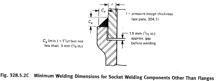
Q39- What is the gap requirement for socket welds in new construction?
Answer:
The required gap for socket welds in new construction is 1.5 mm to 3.0 mm as per ASME B31.3 Fig. 328.5.2C.
📏 Explanation:
Before welding, a gap must be maintained between the pipe end and the bottom of the socket.
This gap:
Allows thermal expansion of the pipe during welding
Prevents stress buildup that could cause cracking
Ensures code compliance
🔧 How to Measure the Gap:
Use a feeler gauge to check the clearance between the pipe end and the socket bottom before welding.
A typical required gap is:
Minimum: 1.5 mm
Maximum: 3.0 mm
⚠️ Important Notes:
This requirement applies to socket weld fittings like elbows, tees, and couplings in new construction.
Not maintaining the gap may result in:
Inspection failure
Weld defects
Non-compliance with ASME B31.3
✅ Summary:
Requirement
Value
Socket Weld Gap (New Construction)
1.5 mm to 3.0 mm
Reference Code
ASME B31.3 Fig 328.5.2C
Q40- Give examples of unique support details that allow piping freedom ofmovement for thermal expansion
Answer:
Piping systems experience thermal expansion and contraction due to temperature changes. To prevent stress or damage, special types of supports are used that allow controlled movement while maintaining system integrity.
✅ Examples of Support Details Allowing Thermal Movement:
Guide Support
Allows axial movement of the pipe while restricting lateral movement.
Maintains alignment but allows pipe to expand/contract in one direction.
Moving Saddle Support
A curved saddle sits on a smooth or low-friction base.
Pipe can slide freely over the saddle as it expands or contracts.
Expansion Bellows (or Bellows Expansion Joints)
Flexible metallic elements that absorb axial, lateral, and angular movement.
Designed specifically to handle thermal expansion stresses.
Shoe Support (Pipe Shoes)
Lifts the pipe off the structure, reducing heat transfer to the support.
When combined with Teflon/PTFE liners or rollers, it allows sliding movement.
Spring-Loaded Supports (Spring Hangers or Supports)
Use of variable or constant load springs to support the weight of the pipe while allowing vertical movement.
Essential for hot lines that rise during operation.
📌 Summary Table:
Support Type
Movement Allowed
Purpose
Guide Support
Axial only
Controls lateral movement
Moving Saddle
Axial (sliding)
Frees pipe to move on saddle
Expansion Bellows
Axial/Lateral/Angular
Absorbs expansion, prevents stress
Pipe Shoe
Axial (when slidable)
Elevates pipe, allows sliding if lined
Spring Support
Vertical movement
Balances load during thermal changes
Q41- When will you apply a 24-hour recorded hydro test?
Answer:
A 24-hour recorded hydrostatic test is applied in specific cases where underground (UG) piping cannot remain fully exposed during pressure testing due to safety or site constraints.
✅ Condition for Applying 24-Hour Hydro Test:
If, for justifiable safety reasons, the underground piping must be backfilled before hydrotesting, then:
The joints shall remain exposed, or
A 24-hour continuous recorded pressure test must be conducted.
🛠️ Purpose of 24-Hour Recorded Test:
Provides a continuous pressure log to prove system integrity.
Ensures that there are no leaks or pressure drops over the extended time.
Satisfies code and client requirements when normal visual inspection is not possible.
📌 Key Points:
Item
Description
When Used
When UG piping is backfilled before testing
Alternative Option
Keep joints exposed during normal test
Duration
24 continuous hours
Requirement
Pressure recording chart or digital logger
Applicable Code
As per ASME B31.3 or project specifications
Q42- What is the difference between Carbon Steel and Stainless Steel?
Answer:
Carbon Steel (CS) and Stainless Steel (SS) are commonly used piping materials, but they differ in composition, corrosion resistance, temperature range, and cost.
🔩 Carbon Steel (CS):
✅ Composition:
Maximum carbon content: ~0.3%
No significant chromium content
✅ Corrosion Resistance:
Low; not suitable for corrosive environments
Requires external painting or coating
✅ Temperature Range:
Suitable for services up to 350°C
✅ Applications:
General industrial use, water, air, oil, and non-corrosive fluids
✅ Cost:
Low cost compared to stainless steel
🔧 Stainless Steel (SS):
✅ Composition:
Contains minimum 12% Chromium (Cr)
Usually has low carbon content (~0.08%)
✅ Corrosion Resistance:
High due to formation of a passive chromium oxide layer
✅ Temperature Range:
Suitable for corrosive, high-temperature, and cryogenic services
✅ Applications:
Used in chemical, pharmaceutical, food-grade, and marine services
✅ Cost:
More expensive due to alloying elements like chromium, nickel, molybdenum
📊 Comparison Table:
Property
Carbon Steel (CS)
Stainless Steel (SS)
Chromium Content
None or trace
Minimum 12%
Carbon Content
Up to 0.3%
Around 0.08%
Corrosion Resistance
Low
High
Max Temperature
~350°C
Higher (varies by grade)
Cryogenic Use
Not recommended
Suitable
Cost
Low
High
Common Use
Oil, water, air (non-corrosive)
Chemical, food, marine (corrosive)
Q43- What is the Difference Between RT and UT?
Answer:
Both Radiographic Testing (RT) and Ultrasonic Testing (UT) are Non-Destructive Testing (NDT) methods used to detect internal flaws in welds and materials. However, they differ in their principle, application, and detection capabilities.
📸 Radiographic Testing (RT):
✅ Principle: Uses X-rays or Gamma rays to capture an image of internal discontinuities on film or digital detectors.
Some planar defects (e.g., lack of fusion), but not very effective
✅ Advantages:
Provides a permanent visual record (film)
Suitable for complex geometries
⚠️ Limitations:
Not good for detecting tight planar defects (e.g., cracks)
Radiation hazard – requires safety precautions
Not suitable for very thick materials
📡 Ultrasonic Testing (UT):
✅ Principle: Uses high-frequency sound waves that reflect off internal flaws.
✅ Detects:
Both planar defects (e.g., cracks, lack of fusion)
And volumetric defects
✅ Advantages:
Accurate depth and size estimation
Detects very small and tight defects
No radiation – safer than RT
Portable and quick
⚠️ Limitations:
Requires skilled operator
Not effective on materials that scatter or attenuate ultrasonic waves (e.g., coarse grain structure)
No visual record unless data is recorded digitally
📊 Comparison Table:
Feature
Radiographic Testing (RT)
Ultrasonic Testing (UT)
Detection Method
X-ray / Gamma ray
Ultrasonic sound waves
Detects
Volumetric defects mainly
Both planar & volumetric defects
Safety Concern
Yes – radiation hazard
No radiation hazard
Material Thickness
Limited for very thick parts
Suitable for thick materials
Operator Skill
Medium
High
Result Output
Film/image
Digital/A-scans
Accuracy of Location
Good for shape
Good for depth, but harder for size
Record Keeping
Film or digital image
Requires digital data capture
Q44- What is the Difference Between PT and MT?
Answer:
Both PT (Penetrant Testing) and MT (Magnetic Particle Testing) are surface inspection methods used in Non-Destructive Testing (NDT), but they differ in application, working principle, and the types of defects and materials they can test.
🧲 Magnetic Particle Testing (MT):
✅ Applicable Materials:
Only for ferromagnetic materials (e.g., carbon steel, low-alloy steels)
✅ Detectable Defects:
Can detect surface and slightly subsurface discontinuities (like cracks, laps, seams)
✅ Advantages:
Faster than PT
Suitable for large surface areas
Works in a wider temperature range
Can detect near-surface defects better than PT
⚠️ Limitations:
Not usable on non-magnetic materials like aluminum, austenitic stainless steel, brass
🟥 Penetrant Testing (PT):
✅ Applicable Materials:
Works on both ferromagnetic and non-ferromagnetic materials
Ideal for non-metallic materials too (e.g., ceramics, plastics)
✅ Detectable Defects:
Detects only surface-breaking defects (e.g., surface cracks, porosity)
✅ Advantages:
Highly sensitive to fine, tight surface cracks
Suitable for a wide range of materials
⚠️ Limitations:
Cannot detect subsurface defects
Requires more steps and time (cleaning, applying, drying, developing)
Effective only within a limited temperature range
📊 Comparison Table:
Feature
Magnetic Particle Testing (MT)
Penetrant Testing (PT)
Material Type
Ferromagnetic only
All materials (metallic & non-metallic)
Detects
Surface & near-surface defects
Surface defects only
Speed
Fast
Slower (multi-step process)
Sensitivity
Moderate
High for fine cracks
Surface Preparation
Moderate
High (clean, dry, develop)
Temperature Range
Wide
Limited
Cost
Low
Moderate
Q45- How Do You Control Material in a Fabrication Shop?
Answer:
Controlling material in a fabrication shop is essential to ensure quality, traceability, and compliance with project and code requirements. Here are the standard steps followed:
✅ 1. Material Identification
All materials must have the material specification and grade either:
Stamped,
Stenciled, or
Marked using a permanent marker.
This ensures easy verification during inspections.
✅ 2. Heat Number Traceability
Every material must have a Heat Number that matches the Mill Test Certificate (MTC).
Only approved vendors must supply the material.
No material substitution is allowed without written approval from the client or QA/QC department.
✅ 3. Storage and Segregation
Materials must be stored separately based on:
Material type
Grade (e.g., CS, SS, Alloy)
Prevents mix-ups and cross-contamination during fabrication.
✅ 4. Heat Number Transfer
Before cutting, the heat number must be:
Transferred to each piece using stamping, tags, or paint marking.
Ensures traceability even after fabrication or cutting.
✅ 5. Color Coding System
Materials are color-coded as per the material traceability procedure.
Each material grade/type has a specific color, making visual identification quick and reliable.
📌 Summary Table:
Control Step
Purpose
Material Spec & Grade Mark
Clear identification
Heat No. Traceability
Match with MTC; ensure origin
Proper Storage
Avoid mixing different grades
Heat No. Transfer Post-Cut
Maintain traceability after cutting
Color Coding
Quick visual recognition
Q46- What are the Inspection Items During Valve Installation
Proper inspection during valve installation is essential to ensure safety, functionality, and compliance with design and project requirements. Below are the key inspection checkpoints:
🔍 1. Valve Type Verification
Ensure the correct valve type (gate, globe, ball, check, etc.) is installed at the designated location.
Must match P&ID and Isometric Drawing.
📄 2. Valve Test Certificate
Verify the availability of valid valve test certificates (hydrostatic, seat leakage, etc.).
Certificates must match the valve tag and specifications.
🔖 3. Valve Tag as per P&ID
Each valve must have a tag number clearly visible and matching the P&ID.
🔁 4. Flow Direction
Check that the arrow marking or flow direction on the valve body is correct as per P&ID flow path.
Especially important for check valves, control valves, and globe valves.
🧰 5. Gasket and Bolt Check
Ensure the gasket type, material, and size match project requirements.
Bolts should be correct in size, grade, and quantity as per isometric drawings.
Torqueing must follow proper procedure.
🔧 6. Handle Position
Valve handle or lever direction must allow easy access and operation.
Should not obstruct adjacent equipment or piping.
🔗 7. Chain Wheel Installation (if applicable)
For valves that are hard to reach, verify that chain wheels are installed and function properly.
🔍 8. Flange Face Condition
Inspect the flange faces for:
Scratches
Rust or damage
Cleanliness
Ensure a smooth and sealed connection.
📋 Optional Additional Checks:
Valve open/close operation check
Lubrication of moving parts if required
Installation of spacers or blinds for spectacle blinds