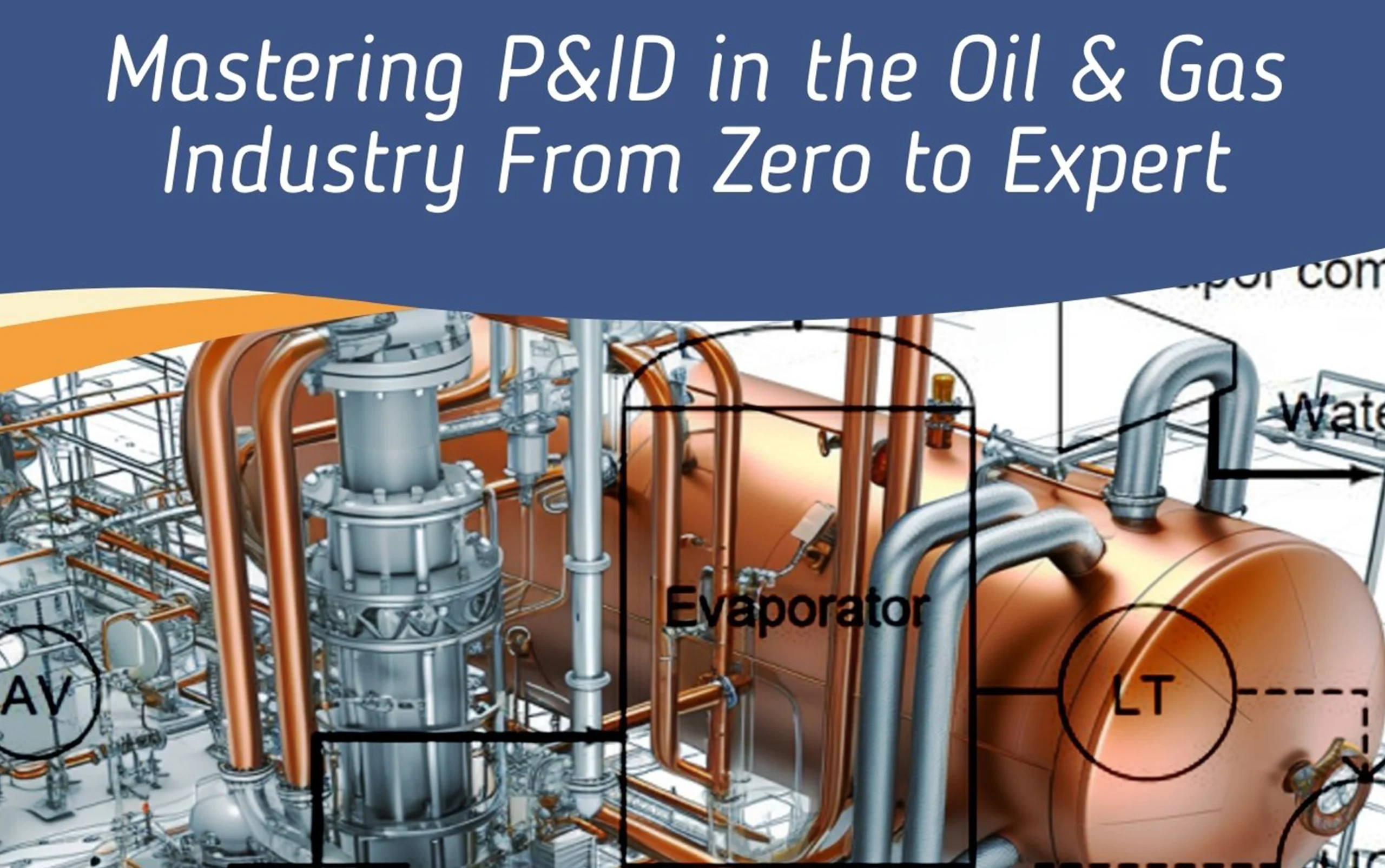
Piping and Instrumentation Diagrams (P&IDs) are vital documents in the oil and gas industry, serving as blueprints for the design, operation, and maintenance of complex process systems. This guide provides an in-depth exploration of P&IDs, covering every essential aspect to help professionals master this critical skill.
What is a Piping and Instrumentation Diagrams (P&ID)?
A Piping and Instrumentation Diagram is a detailed graphical representation of the piping, equipment, instrumentation, and control systems in a process plant. P&IDs are essential tools for engineers, allowing them to visualize the process flow, control systems, and interconnections between different components.
Key Components of P&IDs
1. Piping and Lines in Piping and Instrumentation Diagrams
Piping in P&IDs is represented by different line types and thicknesses, each denoting various types of pipes such as process lines, utility lines, or drain lines. The symbols used for pipes indicate their characteristics, such as diameter, material, and insulation.
2. Instrumentation Symbols in Piping and Instrumentation Diagrams
Instrumentation is a core component of P&IDs, represented by standardized symbols. These include sensors, transmitters, control valves, and other devices that monitor and control process variables like pressure, temperature, and flow.
3. Equipment Symbols in Piping and Instrumentation Diagrams
P&IDs use specific symbols to represent equipment such as pumps, compressors, heat exchangers, and tanks. Each symbol provides essential information about the equipment’s function and specifications.
4. Control Loops
Control loops are crucial in maintaining process stability. In P&IDs, control loops are represented by a combination of instruments and controllers that work together to regulate process variables.
5. Valve Symbols
Valves control the flow of fluids in a process system. P&IDs include various valve symbols, each representing different types such as gate valves, ball valves, and control valves. The position of these valves on the diagram is critical to understanding the process flow.
6. Process Flow Paths
Process flow paths in P&IDs show the direction of process streams. Arrows indicate the flow direction, and different line styles or colors may represent different types of process fluids.
Understanding P&ID Notations and Tags
Tagging System
P&IDs use a tagging system to uniquely identify each component within a process system. Tags typically consist of a combination of letters and numbers that convey information about the equipment type, location, and function.
Common Notations
- Instrument Tags: Indicate the type and function of instruments (e.g., PT for Pressure Transmitter).
- Equipment Tags: Provide identification for equipment (e.g., P for Pump, V for Vessel, E for Exchanger).
Developing and Interpreting P&IDs
Step-by-Step Process for Creating P&IDs
- Define Process Requirements: Begin by understanding the process requirements, including flow rates, pressure, temperature, and the chemical composition of fluids.
- Draft Initial Layout: Create an initial layout of the process using basic symbols for equipment and piping.
- Add Instrumentation and Control Systems: Incorporate the necessary instrumentation and control systems to monitor and manage the process.
- Review and Revise: Collaborate with other engineering disciplines to review the P&ID for accuracy and completeness. Make necessary revisions to ensure the diagram meets all design and safety requirements.
- Finalize the P&ID: Once all revisions are made, finalize the P&ID, ensuring it is ready for use in the detailed design and construction phases.
Best Practices for Interpreting Piping and Instrumentation Diagram (P&IDs)
- Understand Symbols and Tags: Familiarize yourself with the standardized symbols and tags used in P&IDs.
- Follow the Process Flow: Carefully trace the process flow paths to understand the sequence of operations and interconnections between components.
- Pay Attention to Control Loops: Identify and understand the control loops to grasp how process variables are maintained within desired ranges.
- Review for Safety and Compliance: Ensure that the P&ID complies with relevant industry standards and safety regulations.
Importance of P&IDs in the Oil & Gas Industry
P&IDs are indispensable in the oil and gas industry for several reasons:
- Design and Engineering: P&IDs serve as the foundation for designing process systems, ensuring all components are correctly specified and integrated.
- Operation and Maintenance: Operators rely on P&IDs to understand the process flow, control systems, and interconnections, which is crucial for safe and efficient plant operation.
- Safety and Compliance: P&IDs play a vital role in ensuring that process systems comply with safety regulations and industry standards, helping to prevent accidents and ensure operational integrity.
- Troubleshooting and Problem-Solving: Engineers use P&IDs to troubleshoot issues within the process system, quickly identifying the root cause of problems and implementing solutions.
Conclusion
Mastering P&IDs is essential for professionals in the oil and gas industry, as these diagrams are key to the successful design, operation, and maintenance of complex process systems. By understanding the components, symbols, and best practices for developing and interpreting P&IDs, engineers can ensure the safe and efficient operation of process plants.
Read Also
Download Free Piping PDF for Interview Preparation
Download Free Piping PDF for Interview Preparation
What is gasket and their types
What is a valve and its types?


1 thought on “How to read Piping and Instrumentation Diagrams (P&ID): Top 4 Best Practices”